


Design Improvements and Performance Validation of a Competitive Hybrid FSAE Vehicle
Project Title
Design Improvements and Performance Validation of a Competitive Hybrid FSAE Vehicle
University
University of Idaho
Principal Investigator
Dylan Rinker, Steven Beyerlein, Edwin Odom, Herb Hess
U of I Electrical & Computer Engineering
PI Contact Information
U of I Electrical & Computer Engineering
Funding Sources and Amounts Provided
US Department of Transportation — $95,593
University of Idaho — $95,593
Total Project Cost
$191,186
Agency ID or Contract Number
DTRT12GUTC17 UI-KLK908
Start Date
1/1/12
End Date
10/30/14
Description of Research Project
The 2013-2014 Vandal Hybrid Racing team’s mission is to engineer a high performance hybrid racecar capable of competing with comparable FHSAE vehicles. The team’s previously designed and developed powertrain was used; featuring a unique packaging of a Yamaha YZ-250F motorcycle engine with our customized aftermarket electronic fuel injection (EFI), an electric starting system, a limited slip differential, and a centrifugal clutch, Rekluse Z-Start Pro clutching system, which replaces the stock multi-plate wet clutch to allow for aggressive take-offs, coupled at the output shaft to a 46 HP Lynch permanent magnet electric motor creating a post-transmission parallel hybrid drivetrain.
Advancements to this year’s event include an energy management system (EMS), and a drive-by-wire (DBW) system. The EMS is designed and integrated to determine how and when to split the power demand between the available power sources in the hybrid powertrain. The DBW is implemented to idle the ICE during low vehicle speeds and torques.
Implementation of Research Outcomes
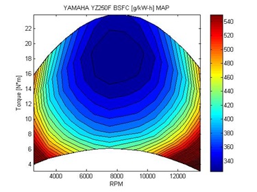
A two-zone numerical model was used to predict performance characteristics of the YZ250F engine. This model employed temperature-dependent specific heat ratios, optimized spark timing, sources of inefficiencies, and valve effects. Mechanical efficiencies were calculated using a linear relationship between engine speed and friction losses, while volumetric efficiencies were fluctuated as a function of engine speed, based on values obtained in previous testing. Based on model predictions, specific fuel consumption maps were developed by running simulations at varying engine operating points. It was found that the YZ250F operated most efficiently at an engine speed of 8000 RPM at a load of approximately 70%. The figure below shows the predicted BSFC map for the YZ250F.
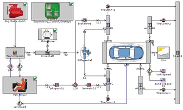
Then the Post Transmission powertrain was modeled as a forward facing model in GT-Suite. The YZ250F was modeled as a map-based engine using the efficiency maps already generated by the two-zone numerical model, an ICE controller was used to simulate engine control functions such as idling and fuel cut off for maximizing fuel economy.
In addition to the same YZ250F engine, a map-based module for the traction motor considering the specification of electrical power request plus an electrical-to-mechanical power conversion efficiency and mechanical friction characteristic. The traction motor is controlled via an electro-mechanical controller which is programmed to follow certain control strategy rules. The brake power necessary to follow a driving cycle is calculated by a power demand template that calculates the necessary tractive power required for a targeted vehicle speed including tire rolling resistance, aerodynamic drag, road curvature and road grade effects.
A model for the battery pack of a capacity of 6 Ah is developed and represented by lookup maps for internal resistance and open-circuit voltage. The battery model calculates the Battery State of Charge (SOC). The SOC is calculated based on the power being drawn from the electric circuit. An inverter is used in conjunction with the battery pack template to ensure the maximum discharge power limit of the battery is not exceeded when it is connected to the electrical or electromagnetic component(s).
A Braking Module is introduced to calculate the brake pedal position based upon the desired braking power, and maximum torque capability of the brakes.
The control system is setup using a rule-based EMS which will be discussed in a later section. The layout of the post-transmission GT-Suite model is shown in the figure below.
DRIVE-BY-WIRE SYSTEM
This year we have chosen to implement a drive by wire system to improve the performance of the powertrain system. Using a DBW system allows for a higher degree of control over the ICE and EM. This system uses two small potentiometers on the accelerator as shown in the figure below, which sends a signal to the EMS which in turn sends a signal to a servo motor on the Bosch 32mm throttle body to put the engine into the correct torque output required by the driver. By using the DBW it is possible to idle the engine during low demand periods and thereby improving fuel economy. Additionally by using the DBW system we can actively control the throttle response of the car for individual drivers and events. The DBW system’s response can be modified by changing the coefficients used in the ECU’s DBW control algorithms. This control ensures that during the endurance race for example the engine will not see a rapid change in throttle position. By smoothing out the changes in throttle position we can keep the engine from accidentally running into a region of poor efficiency that was not intended by the driver.
INTAKE RUNNER
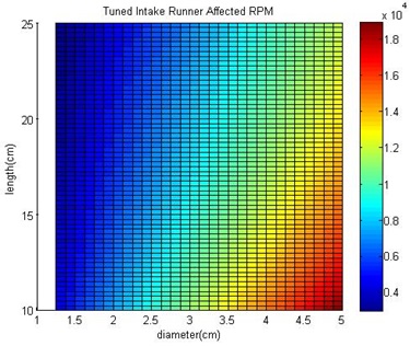
To complement the DBW system we also used a Helmholtz resonator model for a single cylinder to design the intake runner for the ICE. The Helmholtz model is able to predict the RPM point where volumetric efficiency would rise but does not predict the magnitude of the increase.
It became possible to generate a map of possible combinations of diameters and length for the intake runner design shown in the figure below. Using this map we chose to create an intake runner that would allow for the volumetric efficiency increase to occur around the peak torque of the ICE. By placing this phenomenon at the peak torque we hope to increase fuel economy at the point where the engine is likely to spend the majority of its time during normal operation during the endurance race.
HIGH VOLTAGE SYSTEM
The High Voltage System for this was designed to play an assistive role in powering the vehicle. The system utilizes a 110 V, 6 Ah battery pack. The pack fully charged is 120 V and can discharge at a peak of 400 amps, but is limited to 125 amps through the FLNR-125V fuse. The LEM200-D135 RAGS motor used by the system is rated for 110 amps and can produce a peak power of 48 horsepower at around 2300 rpm. SOC is one of the variables that dictate the operation of the EMS, and to capture the SOC we modified the layout of the accumulator to include a current sensor shown in the figure below to allow the BMS to determine the SOC and the draw on the system by monitoring the current draw by the EM. The BMS will in turn send the SOC to the EMS so that the system will know the available energy left in the pack.

ENERGY MANAGEMENT SYSTEM (EMS)
The presence of two alternative power sources, the ICE and the EM, in a HEV poses the problem of determining the optimal power split among them for a given driver request in order to achieve minimum energy consumption.
The previous method of control in the University of Idaho Formula Hybrid racecar (U of I FHSAE) was based on throttle position, where the required torque is split passively between the ICE and the EM. The implication of this system is that the rate at which throttle position demands torque is the only method of adjusting the load between the systems, and no higher level controller is used to determine the torque demand or the proper power split between the two power systems. It was discovered that if the driver turns the acceleration pedal for maximum acceleration, the EM and ICE will produce as much torque as they can. However, in this situation, the efficiency would be reduced and the ICE operating point would not be in the most efficient condition for a period of time.
The new EMS will coordinate the overall powertrain and determine the proper power split between the electrical and thermal energy sources to satisfy the required performance target as shown in the figure below. This is especially important in light of the new endurance event distance, 44 km from the previous 22 km.
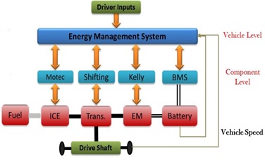
There are several different types of control strategies available; however for ease of implementation and simplicity we designed a rule-based EMS. The power split is generated according to the driver’s commands through throttle position, brake pedal, vehicle speed, engine speed, and SOC of the accumulator. The system will then minimize fuel consumption according to a predesigned set of rules, where the EM operates during low speed-high torque demand and the ICE operates only during higher speeds-higher torque demand. The power split between the two, regulated by the EMS’s rules can vary from 0% to 100%. The designed EMS, shown above, functions by allowing the vehicle to switch the drive system, depending upon throttle position, vehicle speed, and battery SOC, between ICE only mode, electric only, or hybrid mode, in order to achieve the best possible energy efficiency for a given set of conditions.
LOW VOLTAGE, DATA ACQUISITION, and CONTOL BOARD
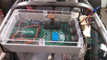
A custom Printed Circuit Board (PCB) inside a waterproof container houses a Microchip™ PIC32 microprocessor packaged on a Digilent™ MAX32™ prototyping platform along with isolation and latching circuitry. This makes up the low voltage system as shown in the figure below.
The processor simultaneously manages the following tasks:
- Energy Management
- Data acquisition
- Data storage
- User Interface
- Fault Checking
The microcontroller reads driver input from the throttle, brake, and shift buttons. This input data is then added to current state data to include SOC, speed, and revolutions per minute, acceleration, and gear number. These parameters dictate the requested throttle output to the ICE and EM controllers.
The data is also used for data acquisition. Upon driver request, the parameter values are sent to a USB host and stored on a dash mounted flash drive allowing for easy development.
The microcontroller utilizes five different types of sensors: Hall Effect, accelerometer, switch, potentiometer, and PWM. A Hall Effect gear tooth sensor was mounted on each rear wheel to monitor the vehicle speed and wheel rpm. An accelerometer was hard mounted to the chassis to measure the acceleration and dynamic performance parameters. Along with these sensors, the microcontroller interfaces with numerous peripheral devices to obtain data to include the EM controller, BMS, and user button input. The data acquired by these sensors are used in the real-time control of the vehicle and in the post-race data analysis.
The management scheme uses a state machine to determine throttle parameters. There are 3 possible states of operation: electric only, ICE only and hybrid electric. The management rules analyze the throttle request and the current state of the vehicle and determine which mode is best under the conditions. The calculated throttle outputs are then sent to the Kelly EM controller and the MOTEC ICE controller over a 0-5V analog line.
Onboard the LVB is the latching circuit. This analog system ensures the safety of the driver and bystanders by preventing undue power up of the HV system. It uses two DPDT relays in a latching configuration. Unless the BMS, GF, and resets are nominal and initiated correctly, the AIRs will not close and the HV system will not send power through the AIRs.
A key aspect of the design and implementation of the distributed control network was to create a modular system that allows for easy debugging, quick swapping of components, simple assembly, and testing of components on and off the vehicle. To meet these goals the electronics are housed in an easily accessible plastic container that uses quick disconnect couplers. This allows for the entire system to be installed on the car in less than a minute.
BRAKING SYSTEM
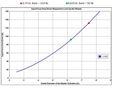
Using data collected from last year’s roll down test, we determined the rolling resistance of the vehicle was far greater than we had anticipated. By going over the drive systems, we determined that the largest contributor to the rolling resistance was caused by rotor drag. The rotor drag is formed from the brake pads still being in contact with the rotors while the brakes are no longer depressed. To decrease the rolling resistance and improve the performance of the braking system we have redesigned the braking system to include new Kart Calipers from Wilwood. These Kart calipers are designed specifically for racing. A unique self-retracting and adjusting piston system enables the piston to retract as the brake line pressure is reduced. Additional features include deep cup stainless steel pistons for reduced heat transfer, cotter pin, pad retainer, internal fluid passage and blue anodized finish.
Impacts and Benefits of the Project
The research and construction of the 2014 Formula Hybrid vehicle has brought about the creation and implementation of two useful models. The first is a two phase engine model created using Matlab that allows users to predict the performance of an engine over an operating range. The model also allows users to create a theoretical Brake Specific Fuel Consumption map based upon theoretical data collected. The user is also able to generate emission maps from the same data. This allows for small and quick modifications to engine component design and model the effects upon the performance and emissions of an engine. This theoretical data can then be verified using a dynamometer. From initial testing data of forty points we observed an average error less than two percent.
The second model was created using the GT Suite program that modeled the Energy Management system used on the vehicle for the 2014 competition year. The model predicts the performance of the hybrid system under different power splits over a specified drive cycle. Using the built in optimization program several simulations were conducted using different power splits to find the optimal power split for a specified drive cycle. This optimization was undertaken as part of the development of the Energy Management system to improve the overall efficiency of the 2014 vehicle.
Several other smaller models were also developed in the course of the year to help advance the 2014 vehicle and to complement past research done with the vehicle. The braking model was updated for the year to model the new braking systems components and improved performance. Along with the engine modifications a simple model of the intake runner was also developed to determine the length and diameter of the runner. This model predicts an improvement in volumetric efficiency over a large range of diameters and lengths which allowed designers to pick an operating point were the vehicle is likely run most during normal operation.
The project was well received at the 2014 competition receiving several trophies and awards. The vehicle received the 1st place overall Hybrid trophy as well as second place in the design event. The vehicle also received the second highest powertrain score in the design event and the only perfect score for aesthetics. Representatives from industry also awarded the vehicle with Chrysler’s first place Innovative Powertrain award and General Motors first place Best Engineered Hybrid Systems award both of which came with cash prizes totaling around $4,500.
Web Links
Final Report: UI_TranLIVE Final Report_CombinedYear1_Year2_FHSAE_KLK908
http://www.formula-hybrid.org/
http://vandalhybridracing.weebly.com/
http://mindworks.shoutwiki.com/wiki/FHSAE_Voltz_N_Boltz
Keywords
- Hybrid vehicle design
- energy management
- vehicle performance testing
- parallel hybrid